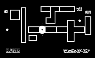


50 Watts FM broadcast (87,5-108MHz) RF-amplifier
Resistors
(values in Ohms unless otherwise noted)
R1 = 100 (0,5W)
R2 = 100 (0,5W)
Capacitors
C1,C4 = 65pF trimmer capacitor, yellow (Philips)
C2,C9,C15,C16,C20,C21 = 10pF
C3,C19 = 33pF
C5,C6,C7,C8 = 100pF
C10 = 470pF
C11 = 100nF/100volts
C12 = 47uF/25volts
C13,C14 = 1nF
C22,C23,C24 = 10pF
C17,C18 = 65pF trimmer (Arco)
Semiconductors
T1 = BLW60 or BLW60(C)
Coils
L1 = 1 turn, 10 mm diameter, 1,5 mm CuAg
L2 = 7 turns, 3 mm diameter, 0,5 mm CuL (closewound)
L3 = 4 turns, 8 mm diameter, 1 mm CuAg (1 mm wire spacing)
L4 = 4 turns, 7 mm diameter, 1 mm CuAg (1 mm wire spacing)
L5 = 4 turns, 9 mm diameter, 1 mm CuAg (1 mm wire spacing)
RFC = VK200 choke
Notes
CuAg = silver plated copper wire
CuL = magnetwire, enameled copper wire
(Note: 1 mm CuL equals approx. to AWG18
0,3 mm equals approx. to AWG28)
(I) all diameters are measured from the inside of the coils
(II) make sure to mount the rf-transistor on a appropriate heatsink and use some thermal
heatsink compound between the stud of the rf-transistor and the heatsink!
(Thermal resistance heatsink at least 6°C/W.)
(III) all parts are soldered directly on the toplayer of the pcb.
PCB: 120 x 74 mm (width x height)
Use FR-4 double sided photoresist epoxy pcb material for best results.
skip to main |
skip to sidebar


 Postingan

 Postingan
Perjalanan & Cerita Hidupku
Belajar dari pengalaman dan Kesalahan.

Favorite Link
Anggota Blog ini
Link Langganan


Blog Archive
-
►
2009
(1)
- ► 04/12 - 04/19 (1)
-
►
2008
(5)
- ► 12/21 - 12/28 (2)
- ► 11/30 - 12/07 (1)
- ► 09/14 - 09/21 (1)
- ► 08/31 - 09/07 (1)

